
Air compressor discharge piping may seem simple, but it actually involves multiple factors: pipe diameter calculation, material selection, slope design, and backflow prevention. A mistake in any one area leads to excessive pressure drop, insufficient air supply to end-use equipment, or even frequent compressor loading/unloading and soaring energy costs. This article provides systematic connection solutions for two critical sections: compressor to receiver tank, and receiver tank to main header.
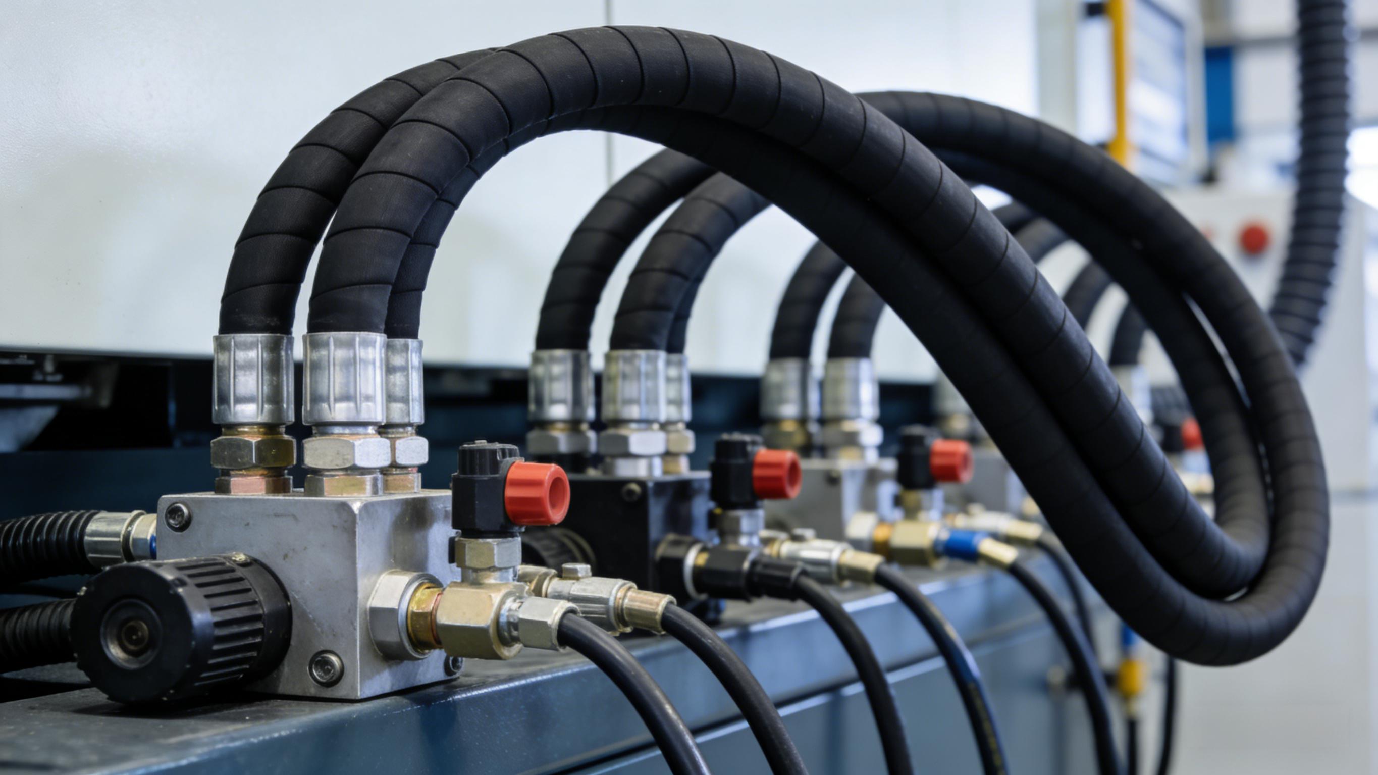
1. Pipe Diameter Selection: From “Sufficient” to “Generous Margin”
The first principle of discharge piping: oversize the pipe diameter whenever in doubt. Total pressure drop in the piping system must not exceed 5% of the compressor’s set pressure, so selecting a larger diameter is always recommended. In practice, while the compressor discharge port is often G1¼ thread, the recommended pipe size should be enlarged to G1½ or G2. If the supply line matches the compressor outlet size, the pipe length should not exceed 50 meters. For longer distances, the main header diameter should be enlarged to two to three times the compressor outlet diameter.
At system pressures below 1.5 MPa, compressed air velocity in the pipe should be kept within 15 m/s to avoid excessive pressure drop. Pipe diameter calculation must consider three variables: flow rate, pipe length, and allowable pressure drop — never apply formulas mechanically.
2. Pipe Material Selection: Stainless Steel Preferred, Carbon Steel for Specific Scenarios
Pipe material selection depends on the required air purity level. Per GB50029-2014 Code for Design of Compressed Air Station: For air quality ≤ Class 5, carbon steel pipe is acceptable; for drying and purification systems with air quality > Class 5 but ≤ Class 3, hot-dip galvanized steel or stainless steel is required; for high-purity systems > Class 3, stainless steel or copper pipe is mandatory.
In industrial practice, stainless steel is strongly recommended — it resists corrosion and effectively reduces leak points. If cost is a constraint, PVR plastic pipe may be used, but additional supports are needed to prevent sagging and water accumulation over time.
3. Compressor → Receiver Tank: Sequence and Valve Arrangement
Correct connection sequence: Compressor → Receiver Tank → Filter → Dryer → After-treatment equipment. Placing the receiver tank before the dryer serves two critical functions: first, the tank volume allows compressed air to cool, condensing part of the water vapor into liquid water that drains from the tank bottom; second, the tank acts as a primary oil-water separator, with air entering from the bottom and exiting from the top while oil-water mixtures settle at the bottom.
Valve configuration: A shut-off valve must be installed between the compressor and receiver tank for maintenance isolation. A check valve must be installed at the compressor discharge to prevent high-pressure air from flowing back into the compressor during shutdown.
Receiver tank sizing: Under normal conditions, receiver tank capacity should be approximately 20% of the compressor’s displacement. If air demand fluctuates sharply, capacity should be ≥20% of the instantaneous peak demand. Another empirical rule is 1/3 to 1/5 of the compressor’s output.
4. Receiver Tank → Main Header: Slope, Branch Lines, and Ring Main Design
Main header slope: The main header must have a 1°–2° slope toward drain points to allow condensate to flow naturally for removal. The minimum slope should not be less than 0.002 (2 mm drop per meter).
Branch line connection: Branch lines must be taken off from the top of the main header, forming a “gooseneck” shape. This prevents condensate from the bottom of the main line from being carried into the end-use equipment by the airflow.
Header size transition rule: The main header must not be reduced in diameter arbitrarily. If reduction is unavoidable, a gradual reducer or expander must be used. Otherwise, turbulence at the connection point causes a sharp increase in localized pressure loss and accelerates pipe wear.
Ring main advantage: The ideal design is a ring main that encircles the entire plant. The ring main acts like a pressure vessel, ensuring balanced pressure at all points. When one branch suddenly draws more air, the ring main can supply from both directions simultaneously, effectively reducing pressure drop. Proper valves should be installed on the ring main to allow partial isolation during maintenance.
5. Condensate Drainage and Pressure Drop Control
Install a ball valve or automatic drain valve at the end of the main header for regular condensate removal.
System pressure drop should be controlled within 10% of the compressor’s discharge pressure (per GB50029-2014).
Minimize the use of 90° elbows, gate valves, and other high-resistance components in the piping.
The minimum main header inner diameter must consider both total pipe length and the plant’s total air consumption.
Summary
The core principles for air compressor discharge piping selection are: oversize the pipe diameter, match material to purity grade, slope for condensate drainage, take branch lines from the top, use gradual reducers for transitions, and place the receiver tank before the dryer. Following this logic ensures controlled pressure drop, stable air supply, and safe equipment operation—making the compressor station’s “respiratory system” truly unobstructed.
