
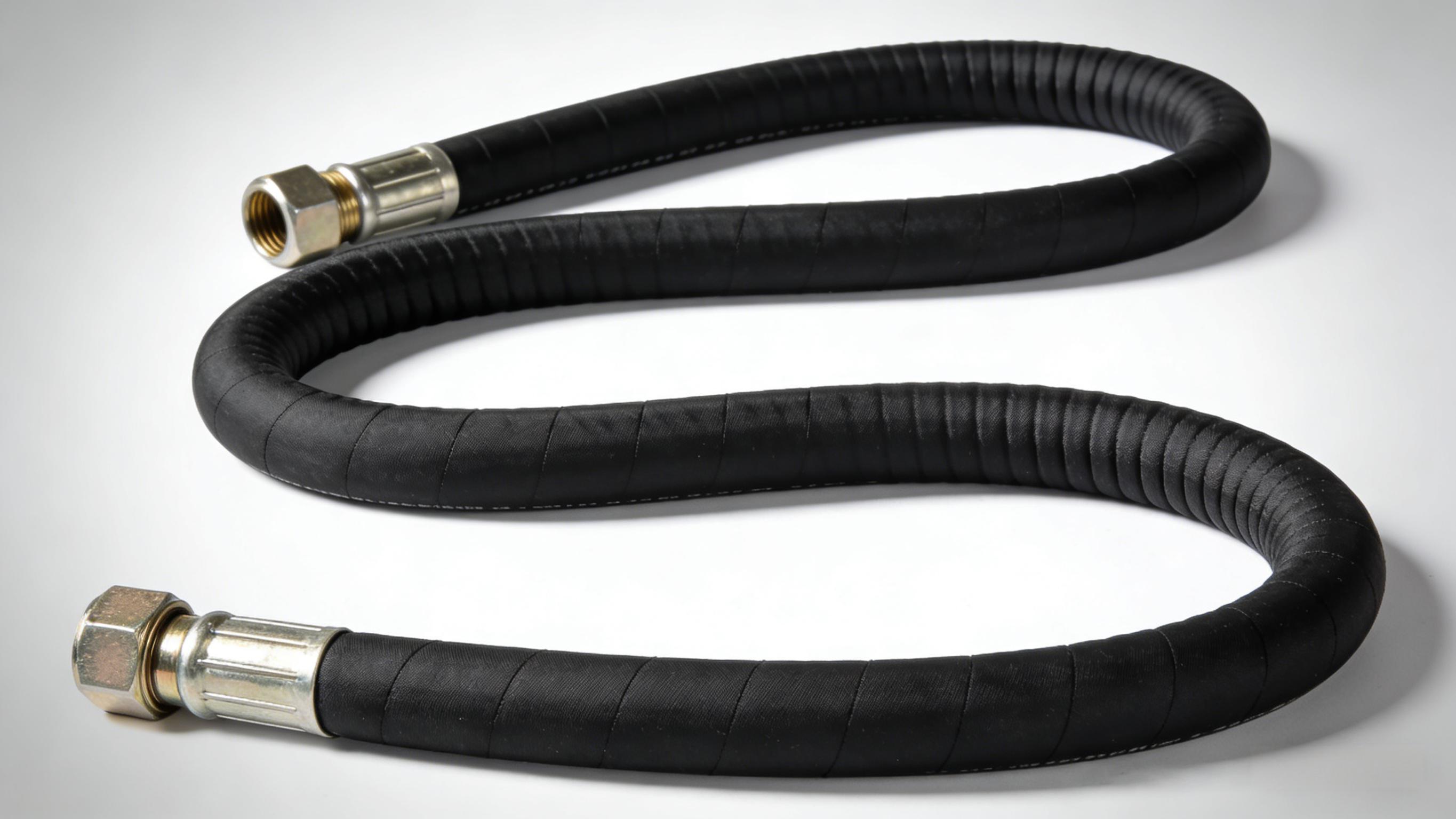
In high-pressure hydraulic systems, 4-spiral wire reinforced hoses (such as 4SP and 4SH) are tasked with transmitting pressures of tens or even hundreds of megapascals. If the crimping process is substandard, the risks of fitting blow-off, leakage, or even burst are imminent. The complex structure of 4-layer steel wire reinforcement and its unique interlayer stress distribution demand a systematic approach — from structural design, crimping parameters, to process control — to guarantee a secure connection.
1. Core Anti-Loosening Principle: The “Interlocking Effect” Between Metals
A 4-spiral wire hose assembly consists of three components: stem, ferrule, and hose. The key to preventing blow-off lies in the ferrule‘s internal tooth profile penetrating through the outer rubber layer to engage directly with the steel wire reinforcement, creating a metal-to-metal locking mechanism. Traditional non-skive crimping relies on friction from the outer rubber to transfer pressure — but under high-pressure impulses, rubber creep causes crimp force decay. Skive crimping, which removes the outer rubber layer to expose the steel wires before crimping, allows the ferrule teeth to bite into the wire gaps, generating exceptionally high pull-out resistance. This is the preferred process for 4-spiral wire ultra-high-pressure hoses.
2. Precise Crimp Reduction Control: The “Mathematical Code” of Anti-Loosening
Too little crimp reduction results in insufficient bite force; too much reduction damages the inner rubber or the steel wires. For 4-spiral wire hoses, the recommended compression factor is approximately 0.6. The crimped diameter can be expressed as: Crimped OD = Pre-crimp OD – Adjustment Value, where the adjustment value must be calculated based on wire layers, ferrule ID, and stem OD. The compression ratio for 4-layer steel wire hoses is typically controlled within 0.5–0.54. Quantitative crimp reduction control is the critical step that transforms “experience” into “standard.”
3. Structural Optimization: Groove Locking Design of Ferrule and Stem
The groove profile on the ferrule’s inner wall directly affects pull-out resistance. For 4-spiral wire hoses, trapezoidal groove ferrules outperform square or wave-shaped profiles — during crimping, the steel wires are forced into the trapezoidal grooves, creating a “barb” effect that significantly enhances pull-out resistance. The stem‘s outer surface is also designed with multiple grooves; during crimping, the inner rubber flows into these grooves, compressing against the ferrule’s raised surfaces to achieve dual internal and external locking. Recent finite element-optimized designs with arc-transition ferrule profiles further reduce stress concentration in the inner rubber layer, extending impulse fatigue life beyond 1 million cycles.
4. Process Verification: The Final Quality Control Loop
After crimping, 100% static pressure testing (typically 1.5× working pressure hold) and batch impulse sampling tests must be performed. A 2003 technology evaluation highlighted a refined design methodology that used finite element simulation to identify stress concentration mechanisms in the inner rubber layer. This led to the “equal strain” design principle between the steel wire layer and the inner rubber layer, substantially improving assembly reliability.
Summary
Ensuring that a 4-spiral wire hose assembly does not loosen relies on a combination of skiving to expose steel wires + precise crimp reduction control + trapezoidal-groove ferrule + dual-locking stem + 100% pressure testing. The core principle is to create metal-to-metal interlocking between the ferrule and the steel wire reinforcement — not friction-dependent compression. Crimping is never “just squeeze it tight”; it is the result of precise calculation and rigorous validation.
